How Gears Work

By: Karim Nice & Kristen Hall-Geisler  | 
gears
Gears are a fundamental part of just about any mechanical object. matejmo/Getty Images

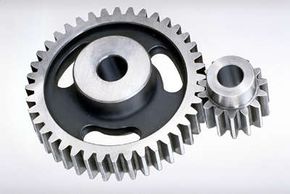
Gears are used in tons of mechanical devices. Most importantly, they provide a gear reduction in motorized equipment. This is key because often a small motor spinning very fast can provide enough power for a device, but not enough torque, the force that causes an object to rotate on an axis or twist. For instance, an electric screwdriver has a very large gear reduction (reduction in the speed of a rotary machine such as an electric motor) because it needs lots of torque to turn screws. But the motor only produces a small amount of torque at a high speed. With a gear reduction, the output speed can be reduced while the torque is increased.

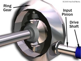
Gears also change the direction of rotation. For instance, in the differential between the rear wheels of your car, the power is transmitted by a shaft that runs down the center of the car, and the differential has to turn that power 90 degrees to apply it to the wheels.

Advertisement

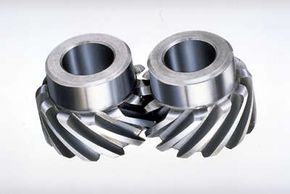
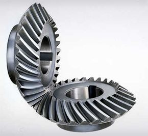
There are a lot of intricacies in the different types of gears. In this article, we'll learn exactly how the teeth on gears work, and we'll talk about the different types of gears you find in all sorts of mechanical gadgets.

Gear Basics

You've probably heard of gear ratios, especially when it comes to cars. The gear ratio is the number of turns the output shaft makes while the input shaft turns one time. If the gear ratio is 2:1, then the smaller gear is turning two times while the larger gear turns just once. It also means that the larger gear has twice as many teeth as the smaller gear. The larger gear is just called a "gear" while the smaller gear is also called a pinion.

One of the most primitive types of gears we could look at would be a wheel with wooden pegs sticking out of it. The problem with this type of gear is that the distance from the center of each gear to the point of contact changes as the gears rotate. This means that the gear ratio changes as the gear turns, meaning that the output speed also changes. If you used a gear like this in your car, it would be impossible to maintain a constant speed — you would be accelerating and decelerating constantly.

Advertisement

Many modern gears use a special tooth profile called an involute. This profile has the very important property of maintaining a constant speed ratio between the two gears. Like the peg wheel above, the contact point moves, but the shape of the involute gear tooth compensates for this movement.

Now let's look at some of the different types of gears.

Advertisement

Spur Gears

Spur gears
Spur gears
Photo courtesy Emerson Power Transmission Corp.

Spur gears are the most common type of gears. They have straight teeth and are mounted on parallel shafts. Sometimes, many spur gears are used at once to create very large gear reductions.

Spur gears are used in many devices that you can see all over HowStuffWorks, like the electric screwdriver, dancing monster, oscillating sprinkler, windup alarm clock, washing machine and clothes dryer. But you won't find many in your car.

Advertisement

This is because the spur gear can be really loud. Each time a gear tooth engages a tooth on the other gear, the teeth collide, and this impact makes a noise. It also increases the stress on the gear teeth.

To reduce the noise and stress in the gears, most of the gears in your car are helical, which we'll explain next.

Advertisement

Helical Gears

Helical gears
Helical gears
Photo courtesy Emerson Power Transmission Corp.

The teeth on helical gears are cut at an angle to the face of the gear. When two teeth on a helical gear system engage, the contact starts at one end of the tooth and gradually increases as the gears rotate, until the two teeth are in full engagement.

The gradual engagement of helical gears makes them operate much more smoothly and quietly than spur gears. For this reason, helical gears are used in almost all car transmissions.

Advertisement

Because of the angle of the teeth on helical gears, they create a thrust load on the gear when they mesh. Devices that use helical gears have bearings that can support this thrust load.

The bent teeth of helical gears means they have to be staggered, with the teeth of the next gear going in the opposite direction so the teeth can mesh. Each gear is called "right-handed" or "left-handed" when it meshes with another gear on parallel shafts. If the angles of the gear teeth are correct, helical gears can also be mounted on perpendicular shafts, adjusting the rotation angle by 90 degrees.

Advertisement

Bevel Gears

Spiral bevel gears
Spiral bevel gears
Photo courtesy Emerson Power Transmission Corp.

Bevel gears are useful when the direction of a shaft's rotation needs to be changed. They are cone-shaped and usually mounted on shafts that are 90 degrees apart, but they can be designed to work at other angles as well.

The teeth on bevel gears can be straight, spiral or hypoid. Straight bevel gear teeth actually have the same problem as straight spur gear teeth — as each tooth engages, it impacts the corresponding tooth all at once.

Advertisement

Just as with spur gears, the solution to this problem is to curve the gear teeth. These spiral teeth engage just like helical teeth: the contact starts at one end of the gear and progressively increases across the whole tooth.

On straight and spiral bevel gears, the shafts must be perpendicular to each other and in the same plane. If you were to extend the two shafts past the gears, they would intersect. The hypoid gear, on the other hand, can engage with the axes in different planes.

Hypoid bevel gears
Hypoid bevel gears in a car differential
HowStuffWorks

This feature is used in many car differentials. The ring gear of the differential and the input pinion gear are both hypoid. This allows the input pinion to be mounted lower than the axis of the ring gear. The figure at left shows the input pinion engaging the ring gear of the differential. Since the driveshaft of the car is connected to the input pinion, this also lowers the driveshaft. This means that the driveshaft doesn't intrude into the passenger compartment of the car as much, making more room for people and cargo.

Advertisement

Worm Gears

Worm gear
Worm gear
Photo courtesy Emerson Power Transmission Corp.

Worm gears are cylinders with a spiral thread wrapped around the outside that meshes with another gear to turn it. They're used when large gear reductions are needed. It is common for worm gears to have reductions of 20:1, and even up to 300:1 or greater.

Many worm gears have an interesting property that no other gearset has: The worm can easily turn the gear, but the gear cannot turn the worm. This is because the angle on the worm is so shallow that when the gear tries to spin it, the friction between the gear and the worm holds the worm in place.

Advertisement

This feature is useful for machines such as conveyor systems, in which the locking feature can act as a brake for the conveyor when the motor is not turning. Worm gears are also used in the Torsen differential, which increases torque for some high-performance cars and trucks.

Rack and Pinion Gears

Rack and pinion gears from a household scale
Rack (straight bar with teeth) and pinion gears from a household scale
HowStuffWorks

Earlier we mentioned that when two gears mesh, the smaller one is called the pinion. A rack is a straight bar with gear teeth that meshes with the pinion . So you can probably imagine how rack and pinion gears are used to convert rotation into linear motion. A perfect example of this is the steering system on many cars. The steering wheel rotates a gear, which engages the rack. As the gear turns, it slides the rack either to the right or left, depending on which way you turn the wheel.

Rack and pinion gears are also used in some scales to turn the dial that displays your weight.

Advertisement

Planetary Gearsets & Gear Ratios

Any planetary gearset has three main components:

  1. sun gear
  2. planet gears and the planet gears' carrier
  3. ring gear

Each of these three components can be the input or the output, or they can be held stationary. Choosing which piece plays which role determines the gear ratio for the gearset. Let's take a look at a single planetary gearset.

Advertisement

One of the planetary gearsets from our transmission has a ring gear with 72 teeth and a sun gear with 30 teeth. We can get lots of different gear ratios out of this gearset.

Gearset table
Gearset table
HowStuffWorks

Locking any two of the three components together will lock up the whole device at a 1:1 gear reduction. Notice that the first gear ratio listed above is a reduction — the output speed is slower than the input speed. The second is an overdrive — the output speed is faster than the input speed. The last is a reduction again, but the output direction is reversed. There are several other ratios that can be gotten out of this planetary gearset, but these are the ones that are relevant to our automatic transmission.

This one set of gears can produce all of these different gear ratios without having to engage or disengage any other gears. With two of these gearsets in a row, we can get as many forward gears and one reverse gear as our transmission needs. We'll put the two sets of gears together in the next section.

Advertisement

Details on Involute Gear Profiles

On an involute profile gear tooth, the contact point starts closer to one gear, and as the gear spins, the contact point moves away from that gear and toward the other. If you were to follow the contact point, it would describe a straight line that starts near one gear and ends up near the other. This means that the radius of the contact point gets larger as the teeth engage.

The pitch diameter is defined as "the imaginary diameter for which the widths of the threads and the grooves are equal," according to ScienceDirect. Since the contact diameter is not constant, the pitch diameter is really the average contact distance. As the teeth first start to engage, the top gear tooth contacts the bottom gear tooth inside the pitch diameter. But the part of the top gear tooth that contacts the bottom gear tooth is very narrow at this point. As the gears turn, the contact point slides up onto the thicker part of the top gear tooth. This pushes the top gear ahead, so it compensates for the slightly smaller contact diameter.

Advertisement

As the teeth continue to rotate, the contact point moves even farther away, going outside the pitch diameter — but the profile of the bottom tooth compensates for this movement. The contact point starts to slide onto the narrow part of the bottom tooth, subtracting a little bit of velocity from the top gear to compensate for the increased diameter of contact. The end result is that even though the contact point diameter changes continually, the speed remains the same. So, an involute profile gear tooth produces a constant ratio of rotational speed.

Frequently Answered Questions

What is gear and why it is used?
A gear is a wheel with teeth along the edge that meshes with another gear to transfer mechanical energy. Gears are used to change the speed, torque, and/or direction of a mechanical system.

Advertisement

Loading...