How An Oscillator Works

By: Marshall Brain  | 
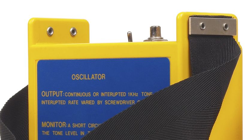
An oscillator output and monitor.
Oscillators produce electronic signals. Hemera Technologies / Getty Images

An oscillator is important in many different types of electronic equipment. For example, a quartz watch uses a quartz crystal oscillator to keep track of what time it is. An AM radio transmitter uses an oscillator to create the carrier wave for the station, while an AM radio receiver uses a special form of oscillator called a resonator to tune into a station.

There are even oscillators in computers, metal detectors and stun guns. To better understand how electronic oscillators work, it is helpful to look at everyday examples around us. In this article, you'll learn the basic principle behind how an oscillator works, plus how they're used in electronics.

Advertisement

The Basic Principle of Oscillator Circuits

The core principle behind oscillator operation is positive feedback combined with an amplification process. Positive feedback refers to the process where a portion of the output signal is fed back into the system's input in a way that reinforces the initial signal.

For an oscillator to start and maintain its operation, the total loop gain of the system — the product of the amplifier gain and the feedback loop's gain — must be equal to or greater than one. Additionally, the phase shift around the loop must sum to a multiple of 360 degrees to ensure the signal reinforces itself with each cycle, leading to sustained oscillation.

Advertisement

The Pendulum Example

One of the most commonly used oscillators is the pendulum of a clock. If you push on a pendulum to start it swinging, it will oscillate at a desired frequency — it will swing back and forth a certain number of times per second. The length of the pendulum is the main thing that controls the frequency.

For something to oscillate, energy needs to move back and forth between two forms. For example, in a pendulum, energy moves between potential energy and kinetic energy. When the pendulum is at one end of its travel, its energy is all potential energy and it is ready to fall. When the pendulum is in the middle of its cycle, all of its potential energy turns into kinetic energy and the pendulum is moving as fast as it can. As the pendulum moves toward the other end of its swing, all the kinetic energy turns back into potential energy. This movement of energy between the two forms is what causes the oscillation.

Eventually, any physical oscillator stops moving because of friction. To keep it going, you have to add a little bit of energy on each cycle. In a pendulum clock, the energy that keeps the pendulum moving comes from the spring. The pendulum gets a little push on each stroke to make up for the energy it loses to friction. An electronic oscillator works on the same principle.
Advertisement

Oscillating Circuits

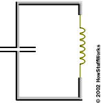
Diagram of oscillator circuits.
The oscillator circuit components at work.

Energy needs to move back and forth from one form to another for an oscillator to work. You can make a very simple oscillator by connecting a capacitor and an inductor together. If you've read How Capacitors Work and How Inductors Work, you know that both capacitors and inductors store energy. A capacitor stores energy in the form of an electrostatic field, while an inductor uses a magnetic field.

Imagine the following circuit:

Advertisement

If you charge up the capacitor with a battery and then insert the inductor into the circuit, here's what will happen:

  • The capacitor will start to discharge through the inductor. As it does, the inductor will create an electromagnetic field.
  • Once the capacitor discharges, the inductor will try to keep the current in the circuit moving, so it will charge up the other plate of the capacitor.
  • Once the inductor's field collapses, the capacitor has been recharged (but with the opposite polarity), so it discharges again through the inductor.

­This oscillation will continue until the circuit runs out of energy due to resistance in the wire. It will oscillate at a frequency that depends on the size of the inductor and the capacitor.

Advertisement

Types of Oscillators

Oscillators can be broadly categorized into two main types: linear (harmonic) oscillators and relaxation oscillators.

Linear oscillators: A harmonic oscillator produces a sinusoidal output. It relies on the principle of resonance, where an LC (inductor-capacitor) or RC (resistor-capacitor) circuit is used to determine the frequency of oscillation. The most common types include the Colpitts, Hartley, and RC Phase Shift oscillators.

Advertisement

Relaxation oscillators: In contrast, relaxation oscillators generate a non-sinusoidal output, such as a square or sawtooth wave. They work by charging and discharging a capacitor through a resistor at a rate determined by the RC time constant. The unijunction transistor (UJT) oscillator and the 555 timer in astable mode are examples of relaxation oscillators.

Of course, there are also more specific types. For example, electronic devices use crystal oscillators, radio frequency oscillators, and voltage controlled oscillators, to name but a few.

Advertisement

Key Components

The operation of an oscillator hinges on several key components:

  • Amplifier: An amplifying device provides the necessary gain to ensure that the loop gain criteria are met for sustained oscillation.
  • Feedback network: Feedback loops determine the frequency of oscillation and ensure the phase shift criteria is met. These networks can be RC or LC oscillators, or crystal circuits.
  • Power supply: This offers the energy needed for the oscillator to function.

Advertisement

What Are Oscillator Waveforms?

Oscillator waveforms refer to the shapes of the electrical signal outputs, or "output waveforms," generated by oscillators. These waveforms are graphical representations of the voltage of the signal over time. The nature of the output waveform produced depends on the type of oscillator and its design.

Each waveform type has its own unique properties and uses. The most common types of oscillator waveforms include sine wave, sawtooth waveform, triangle wave, and square wave.

Advertisement

Resonators

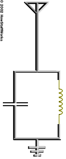
Resonator diagram.
A resonator at work.

In a simple crystal radio (see How Radio Works for details), a capacitor/inductor oscillator acts as the tuner for the radio. It is connected to an antenna and ground like this:

Thousands of sine waves from different radio stations hit the antenna. The capacitor and inductor want to resonate at one particular radio signal. The sine wave that matches that particular frequency will get amplified by the resonator, and all of the other frequencies will be ignored.

Advertisement

In a radio, either the capacitor or the inductor in the resonator is adjustable. When you turn the tuner knob on the radio, you are adjusting, for example, a variable capacitor. Varying the capacitor changes the resonant frequency of the resonator and therefore changes the frequency of the sine wave that the resonator amplifies. This is how you "tune in" different stations on the radio!

Oscillator Circuit: The Heartbeat of Electronics

Oscillators serve as the heartbeat for countless systems and devices. Through the principles of amplification and feedback, they provide the periodic signals necessary for everything from maintaining time in digital circuits to enabling communication across vast distances.

As technology continues to advance, the role of oscillators remains pivotal, driving innovation and enabling new applications in an ever-connected world.

Advertisement

This article was updated in conjunction with AI technology, then fact-checked and edited by a HowStuffWorks editor.

Advertisement

Loading...